MC6883 (74LS783) SAM and MC6847 VDG interaction
The SAM contains circuitry specifically to assist in providing access to memory to the 6847 VDG. By simulating the VDG's memory access pattern in the SAM, only DA0 from the VDG need be connected (state transitions on this line then being enough information to advance the SAM's simulated counter). To do this accurately, the SAM can be told which mode the VDG has been set to. Usually, both chips will be configured to the same mode, but some extra modes can be produced by mismatching their configurations. The SAM data sheet documents some of these extra modes (Semigraphics 8, 12 and 24) but more are available, including some with non-visible bytes on each scanline.
The actual operation of the SAM's video address counter is mostly1 described in the SAM block diagram (figure 4) and following text in the data sheet, but the combined behaviour of the two chips is only explicable when you know that at the end of each scanline, the VDG actually presents several more addresses before the falling edge of HS: ten more in 32-byte video modes, and six more in 16-byte modes.
Here's a trace of the VDG address lines relative to HS for one scanline in a 32-byte mode where you can see 42 addresses presented (41 transitions) before the falling edge of HS:
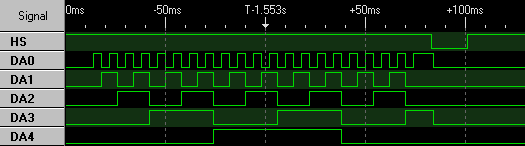
Thanks to Phill Harvey-Smith for capturing this trace.
Notes
The "X" and "Y" dividers in the data sheet (figure 5) do not exactly correspond to the X-axis and Y-axis on screen.
When the SAM clears bits of its internal VDG counter at the end of a scanline, if the topmost of the cleared bits was HIGH before, clearing it will toggle the next bit in the chain. This is the behaviour that enables the 48-bytes-per-scanline mode. Here's an excerpt of a mail I've sent previously attempting to clarify:
If you look at fig. 4 in the SAM datasheet you can see the VDG address is
basically a simple binary counter with the lowest bit clocked off DA0 with
a couple of dividers that divide by varying amounts according to fig. 5 -
not important in this mode, because they are both set to "divide by 1".

In a binary counter, the output from one bit (flip-flop) is used as the
clock to the next: on its falling edge, the state of the next bit toggles.
When the SAM clears the bits as you describe (also from fig. 5), if the
topmost of the bits you clear was previously HIGH, that will effectively
be that falling edge input to the next bit along.

So imagine a line starting at address 0.  Because the VDG has toggled
DA0 41 times ("requested" 42 addresses), the VDG address counter will
look like this:

0000000000101001

now bits 0-3 are cleared:

0000000000100000

But that means bit 3 transitioned 1 to 0 - a falling edge that causes
bit 4 to toggle:

0000000000110000

Et voila!
As ever, of course, it's not quite this simple, although this works for most observable behaviour. More soon, hopefully.↩