Dragon 64 motherboard
Recreation of the Dragon 64 motherboard.
Schematic transcribed into KiCad from the original drawings hosted by Richard Harding.
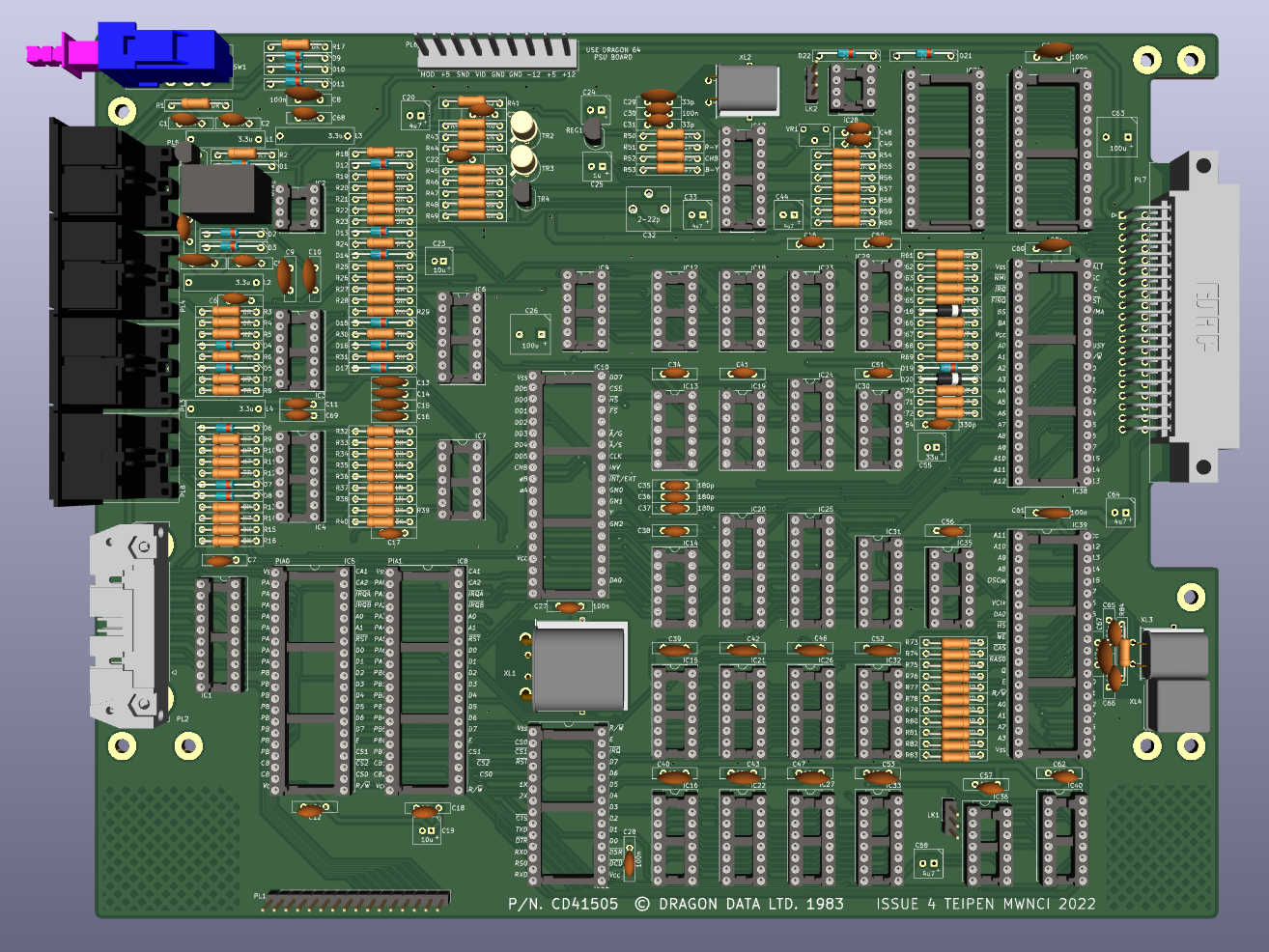
I've tried to make the placement in the PCB layout as close as possible to the original, but routing will be different. I have tried to give adequate trace width and spacing around power, and reasonable clearance for sensitive analogue signals.
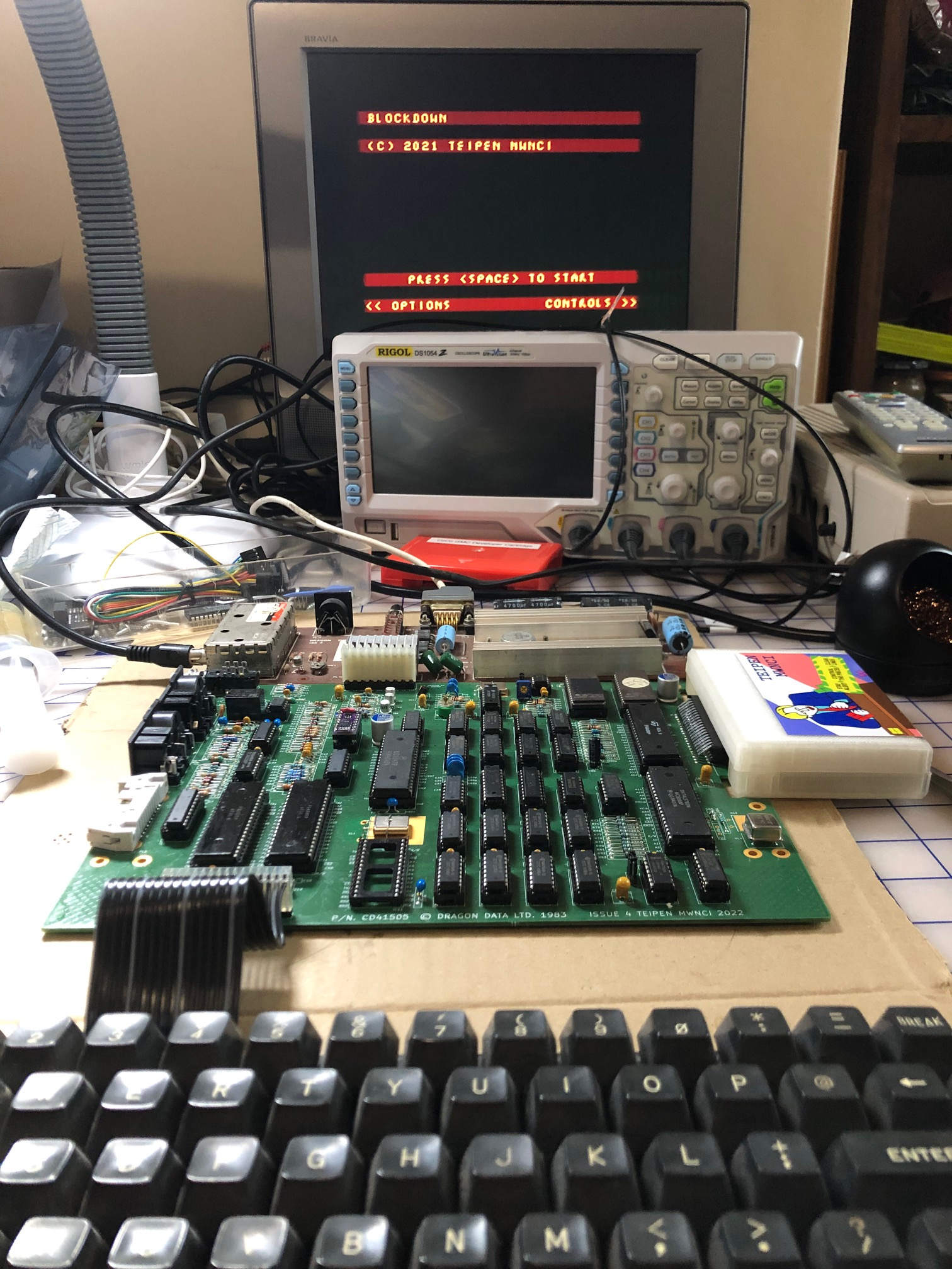
PCB now successfully built and tested by me and at least two other people.
- KiCad 7 schematic and PCB layout - "Issue 6"
- Dragon 64 schematic on gitlab
- PDF version of schematic
- Build video
"Issue 4" requires a single bodge wire due to a transcription error.
My original fix was to connect pins 12 and 17 of the VDG. This ties MS# high meaning DA0 will not float, which seemed like a good idea as I have used an HCT part for IC13.
The original board instead ties it to FS# - connecting pins 12 and 37 of the VDG. This means DA0 will float during vertical sync. As this is not ideal for a CMOS input, try and use an LS part for IC13. It turns out lowercase kits assume that MS# is connected to FS#, so if you wish to use one, you should prefer this fix.
"Issue 5" repositions some mounting holes and fixes the problem mentioned above with the first approach. It was published before the problem with lowercase kits was discovered.
"Issue 6" replaces a couple of jumpers with smaller solder jumper equivalents, and adds two more: one to select between Dragon 32 and Dragon 64 HSync mode, and one to tie MS# either high or to +5V.
The serial and parallel ports have now been tested and appear to work fine.